This article will go a little further than simply saying, "get a card, plug it in". There are a few issues to be concerned about when attempting to retrofit current technology into something as old (and now obsolete) as the IBM 600X laptop. Back when this laptop was new (1999-2000), there weren't too many (if any) laptops with built-in wireless networking. I have searched and the earliest mention of a laptop with this capability is about this Toshiba. This procedure will explain what I did and show you in great detail how you can do this yourself.
 The downsides? Well, first you have to get rid of that old 56K modem that's gathering dust on the bottom side of your 600X.
If you haven't used that RJ-11 jack on the left side of the laptop in ages then you are already halfway there to starting
this conversion. You will also have to spend some time tearing apart your 600X. It's easy really. Just refer to IBM's 600X
Hardware Maintenance Manual in Adobe Acrobat
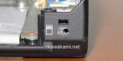
Reader (.PDF) format. When you are done with all of these directions you will also have an antenna jack sticking out the
corner of the laptop just behind the two PCMCIA release buttons. You see where that tiny hole just above the Zoomed Video
logo is? Right there.
The downsides? Well, first you have to get rid of that old 56K modem that's gathering dust on the bottom side of your 600X.
If you haven't used that RJ-11 jack on the left side of the laptop in ages then you are already halfway there to starting
this conversion. You will also have to spend some time tearing apart your 600X. It's easy really. Just refer to IBM's 600X
Hardware Maintenance Manual in Adobe Acrobat
Reader (.PDF) format. When you are done with all of these directions you will also have an antenna jack sticking out the
corner of the laptop just behind the two PCMCIA release buttons. You see where that tiny hole just above the Zoomed Video
logo is? Right there.
The only tools you will need are a small (#0) philips screwdriver, a socket wrench, needle-nose pliers, a drill and a couple of X-Acto ® blades. Total time for the upgrade is about two hours if you work slow and haven't ever torn apart your laptop. The hardware consists of the Mini PCI wireless card and a cable that is connected from the card to the external antenna jack. The driver software and wireless card configuration program are freely available. My recommendation for the wireless card that you should use is based upon this software and also because of the fact that it appears to be supported by NetStumbler. Of course you are free to substitute whatever wireless card you want or have.
With the pictures and instructions I have here, it should be fairly easy to duplicate what I have done if you want your 600X to be wireless and have both PCMCIA slots free. As usual with these kinds of projects, I cannot be held liable for any damage you may incur to your laptop while attempting to follow these instructions! I would be interested in hearing from anyone who has used this procedure or if you have any comments or suggestions. My e-mail address is at the bottom of the page.
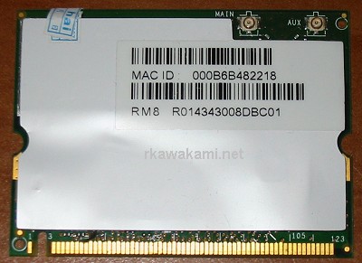 |
| Front side view of BCM94306 wireless card |
 |
| Front view with the label removed |
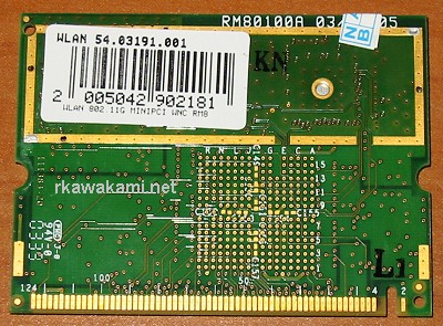 |
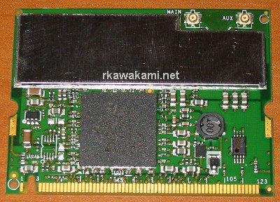
| Back view of BCM94306 wireless card |
I initially had a problem with the driver software the seller had provided. I have found Windows 2000 and XP drivers for it which seems to work quite well. While this card has been obsoleted by Broadcom, there still appears to be a few sites where the Gateway drivers and Belkin driver/configuration programs can be downloaded. If these links go dead, e-mail me and I can provide the files. As I said earlier, if you are using your own card and software then ignore this section. If you do not already have a Mini PCI wireless card then be careful on which one you select. Find out if it comes with the drivers, installation and configuration programs.
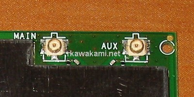 The first thing one finds out when attempting to use a Mini PCI wireless card is, "What do I do for an antenna?". With
the PCMCIA cards, the antenna is of course, built-in and located in the section that sticks out from the laptop. This
insures a clear path for receiving the radio signals (no metal in the way). The Mini PCI wireless cards usually come with
two tiny connectors for antennas called U.FL or
Hirose, after the manufacturer of this connector. The reason for the two antennas
is to support the antenna diversity feature. This means that the wireless card automatically selects the strongest signal
from either antenna. It usually does not matter which connector you use (main or aux) if you are only going to use one
antenna.
The first thing one finds out when attempting to use a Mini PCI wireless card is, "What do I do for an antenna?". With
the PCMCIA cards, the antenna is of course, built-in and located in the section that sticks out from the laptop. This
insures a clear path for receiving the radio signals (no metal in the way). The Mini PCI wireless cards usually come with
two tiny connectors for antennas called U.FL or
Hirose, after the manufacturer of this connector. The reason for the two antennas
is to support the antenna diversity feature. This means that the wireless card automatically selects the strongest signal
from either antenna. It usually does not matter which connector you use (main or aux) if you are only going to use one
antenna.
Because it is not a viable option for Mini PCI wireless cards to dangle a wire outside of the laptop case, some people sell short (2"-3") antennas and say to simply stuff the antenna into the Mini PCI compartment. This might work for those laptops with all plastic cases and door panels, or for someone who uses the laptop in the same room as the access point. The best placement for an internal antenna is where most of today's laptop builders put theirs; in the lid of the laptop. My first attempt at using a Mini PCI wireless card did just that. I took the 600X lid apart, placed one of the antennas that came with my wireless card at the top edge of the LCD, routed the wire down the side of the lid, threaded it out the right side hinge and down into the laptop. I plugged the antenna into the Broadcom card and found that my reception on the opposite side of the house from my WAP was just as good (read: so-so) as my D-Link cards. Bummer. All that work and no improvement.
 Since I did not see any improvement in range with my Broadcom card and "stealth" antenna over my existing D-Link setup,
I decided it was time to look into an external antenna. The only thing I found on the web for a 600X laptop was the person
who removed the PS/2 socket
on the back of the laptop and installed an antenna jack there. Interesting, but for some of my laptops that would not work
because I use them with the Docking Station. I had a motherboard and base for a 600X laying around from another project I
was working on. I looked at what was available, space-wise, for mounting an antenna jack. The obvious solution to me was to
use the back corner of the laptop just behind the PCMCIA card cage. It is close to the Mini PCI socket on the bottom of the
motherboard, sticks out to the side where it wouldn't interfere with the docking station, and where an antenna could be
positioned without having to worry about swinging the display back too far and hitting the antenna. Having identified the
most likely spot for the antenna jack, now it was on to figuring out what to use. There are many different types of
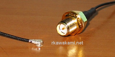
RF connectors being used for attaching antennas and cables. It seems like the majority of removable antennas made for
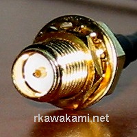
WAPs use what is called "reverse polarity SMA" (RP-SMA) type
connectors. The RP-SMA jack (what gets mounted inside the equipment; picture on the left) consists of a barrel that is
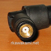
threaded on the outside and a pin in the middle of the interior of the barrel. The RP-SMA
antenna (also could be called the plug; right picture) has matching threads on the inside of the connector
and a hole at the center. So what I needed for the inside of the laptop to connect the Mini PCI card to the
outside world would be a U.FL to RP-SMA cable (or pigtail). A quick search on eBay located a seller with exactly this
type of adapter. I ordered the 12" version as it looked like it was just the right length I needed.
Since I did not see any improvement in range with my Broadcom card and "stealth" antenna over my existing D-Link setup,
I decided it was time to look into an external antenna. The only thing I found on the web for a 600X laptop was the person
who removed the PS/2 socket
on the back of the laptop and installed an antenna jack there. Interesting, but for some of my laptops that would not work
because I use them with the Docking Station. I had a motherboard and base for a 600X laying around from another project I
was working on. I looked at what was available, space-wise, for mounting an antenna jack. The obvious solution to me was to
use the back corner of the laptop just behind the PCMCIA card cage. It is close to the Mini PCI socket on the bottom of the
motherboard, sticks out to the side where it wouldn't interfere with the docking station, and where an antenna could be
positioned without having to worry about swinging the display back too far and hitting the antenna. Having identified the
most likely spot for the antenna jack, now it was on to figuring out what to use. There are many different types of
RF connectors being used for attaching antennas and cables. It seems like the majority of removable antennas made for
WAPs use what is called "reverse polarity SMA" (RP-SMA) type
connectors. The RP-SMA jack (what gets mounted inside the equipment; picture on the left) consists of a barrel that is
threaded on the outside and a pin in the middle of the interior of the barrel. The RP-SMA
antenna (also could be called the plug; right picture) has matching threads on the inside of the connector
and a hole at the center. So what I needed for the inside of the laptop to connect the Mini PCI card to the
outside world would be a U.FL to RP-SMA cable (or pigtail). A quick search on eBay located a seller with exactly this
type of adapter. I ordered the 12" version as it looked like it was just the right length I needed.
 Once I received the adapter I measured all of the critical dimensions and found:
Mounting hole: 0.25"
Barrel length: 0.40"
Overall length: 1.05" (end of barrel to strain relief)
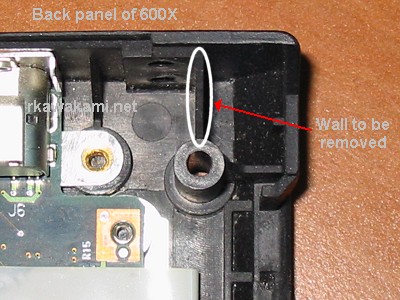 The picture to the left shows the back right corner of the laptop and indicates the wall that needs to be removed so the
RP-SMA jack can be installed.
The picture to the left shows the back right corner of the laptop and indicates the wall that needs to be removed so the
RP-SMA jack can be installed.
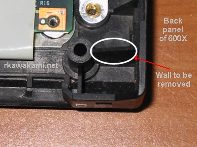 This is the same corner but viewed from the side.
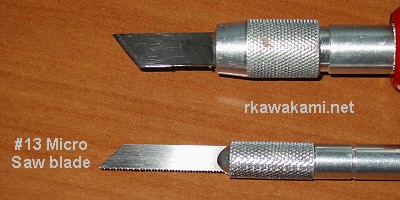 I had considered using my Dremel ® to cut the plastic but there wasn't enough room to get a cutting wheel down into
that corner without damaging adjoining areas and get a straight cut. I also tried my standard X-Acto ® blades but they
wouldn't bite into the plastic. After a little while searching for different blades styles I found a #13 Micro Saw. A
quick run down to D&J Hobby to purchase these blades and in no time, the wall
was gone.
I had considered using my Dremel ® to cut the plastic but there wasn't enough room to get a cutting wheel down into
that corner without damaging adjoining areas and get a straight cut. I also tried my standard X-Acto ® blades but they
wouldn't bite into the plastic. After a little while searching for different blades styles I found a #13 Micro Saw. A
quick run down to D&J Hobby to purchase these blades and in no time, the wall
was gone.
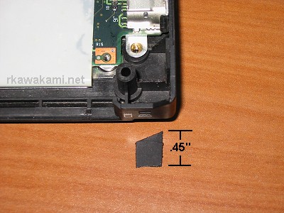 Use the #13 Micro saw to cut down both edges of the wall (about 1/2" on the part connected to the back side of the laptop)
and then score a deep line across the wall between the two cuts and then bend/break the plastic off.
Use the #13 Micro saw to cut down both edges of the wall (about 1/2" on the part connected to the back side of the laptop)
and then score a deep line across the wall between the two cuts and then bend/break the plastic off.
 Next step is to drill the hole on the side of the laptop base. I drilled a pilot hole in the spot that I figured would be
the center of the 1/4" hole. As it turns out, this spot was slightly too low and I had to force the drill up a little
higher.
Next step is to drill the hole on the side of the laptop base. I drilled a pilot hole in the spot that I figured would be
the center of the 1/4" hole. As it turns out, this spot was slightly too low and I had to force the drill up a little
higher.
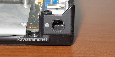 The finished hole is 1/4" in diameter and may need to be slightly enlarged if you have trouble pushing in the jack because
of the angle (the connector doesn't go straight in where I've drilled the hole because of the screw tower). If the hole is
moved a little further toward the back side of the laptop then it might make it easier to mount the jack. However, the base
of the antenna may extend past the back edge of the laptop and prevent use with a docking station. If the hole is drilled
too low then the angled portion of the case will prevent the antenna jack from being mounted flush.
The finished hole is 1/4" in diameter and may need to be slightly enlarged if you have trouble pushing in the jack because
of the angle (the connector doesn't go straight in where I've drilled the hole because of the screw tower). If the hole is
moved a little further toward the back side of the laptop then it might make it easier to mount the jack. However, the base
of the antenna may extend past the back edge of the laptop and prevent use with a docking station. If the hole is drilled
too low then the angled portion of the case will prevent the antenna jack from being mounted flush.
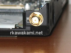
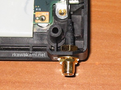
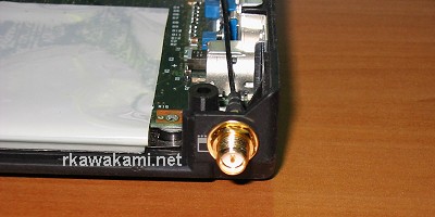 Here is the mounted RP-SMA jack. I found that it was necessary to use TWO lock washers; one on each side of the hole because
the connector would loosen up if the antenna was tightened too hard. A socket wrench and needle-nosed pliers was used to
firmly install the jack. Double-check to see if it is tight enough by spinning on an antenna and trying to over tighten it.
You don't want the jack to loosen up after you re-assemble the laptop. If you are really worried about it coming loose,
you could try to epoxy the jack on the inside. Just pray that the pin inside the jack never breaks.
Here is the mounted RP-SMA jack. I found that it was necessary to use TWO lock washers; one on each side of the hole because
the connector would loosen up if the antenna was tightened too hard. A socket wrench and needle-nosed pliers was used to
firmly install the jack. Double-check to see if it is tight enough by spinning on an antenna and trying to over tighten it.
You don't want the jack to loosen up after you re-assemble the laptop. If you are really worried about it coming loose,
you could try to epoxy the jack on the inside. Just pray that the pin inside the jack never breaks.
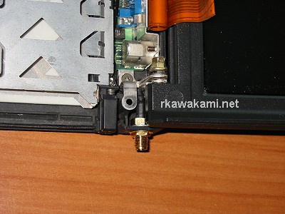
 This is an overview of the mounted RP-SMA jack showing how the jack extends past where the wall used to be. If it looks
like the the end of the strain relief is too far into the laptop case, you're almost right. It's going to be a tight
fit!
This is an overview of the mounted RP-SMA jack showing how the jack extends past where the wall used to be. If it looks
like the the end of the strain relief is too far into the laptop case, you're almost right. It's going to be a tight
fit!
 Here's what it looks like when the LCD panel is re-installed. The bracket that holds the panel to the back side of the
laptop case just fits if the thin coaxial wire of the antenna jack is bent sharply. For Version 2 of this
upgrade I'm going to try to find an RP-SMA jack that isn't as deep.
Here's what it looks like when the LCD panel is re-installed. The bracket that holds the panel to the back side of the
laptop case just fits if the thin coaxial wire of the antenna jack is bent sharply. For Version 2 of this
upgrade I'm going to try to find an RP-SMA jack that isn't as deep.
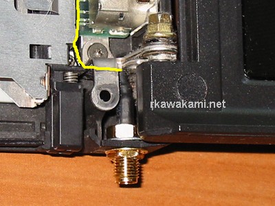 This is a close-up of the installed jack. I've highlighted the cable path in yellow so you can see just how tight the fit
really is.
This is a close-up of the installed jack. I've highlighted the cable path in yellow so you can see just how tight the fit
really is.
 This picture shows the coax wire making the sharp turn from the end of the strain relief and passing around the mounting
bracket for the LCD panel.
This picture shows the coax wire making the sharp turn from the end of the strain relief and passing around the mounting
bracket for the LCD panel.
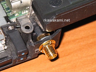
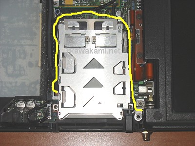 This is the path where I've routed the coaxial wire around the PCMCIA card cage and down through the hole into the Mini
PCI area. There's a small bracket at the upper right corner of the PCMCIA cage which holds down the CPU board. I've routed
the cable under that bracket, next to the motherboard.
This is the path where I've routed the coaxial wire around the PCMCIA card cage and down through the hole into the Mini
PCI area. There's a small bracket at the upper right corner of the PCMCIA cage which holds down the CPU board. I've routed
the cable under that bracket, next to the motherboard.
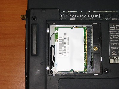 With the Mini PCI wireless card replacing the old 56K modem and the U.FL antenna connector firmly snapped into place,
this laptop is almost ready to go on the air. Only one more modification to the laptop is needed.
With the Mini PCI wireless card replacing the old 56K modem and the U.FL antenna connector firmly snapped into place,
this laptop is almost ready to go on the air. Only one more modification to the laptop is needed.
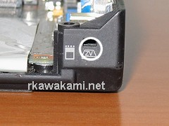
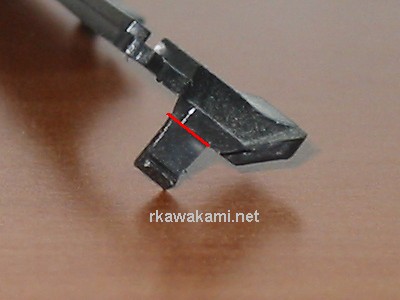 There is a thin bezel which runs the entire length of the top side of the laptop, just beneath the LCD lid. It is normally
clipped into the tiny holes on either side of the case. Now that there is an external antenna jack where one of those
holes used to be, a small modification is in order to the bezel. The tab I have indicated in this picture needs to be
cut off before the bezel is re-installed.
There is a thin bezel which runs the entire length of the top side of the laptop, just beneath the LCD lid. It is normally
clipped into the tiny holes on either side of the case. Now that there is an external antenna jack where one of those
holes used to be, a small modification is in order to the bezel. The tab I have indicated in this picture needs to be
cut off before the bezel is re-installed.
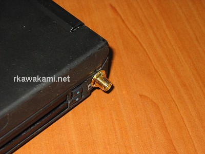 Re-assemble the laptop (not that easy a task if you haven't done it before) and this is what it looks like.
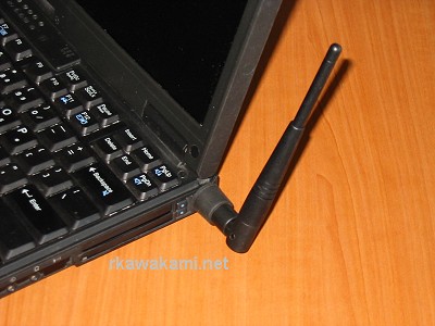 Connect an RP-SMA antenna and you are ready to go! Here I am using one from a Linksys WET11 bridge that happens to be
laying around.
Connect an RP-SMA antenna and you are ready to go! Here I am using one from a Linksys WET11 bridge that happens to be
laying around.
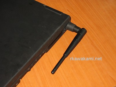 With the antenna down it does seem to stick out fairly far from the side of the laptop. (Note to self: for Version 2,
try to find another antenna that has a shorter base. Or maybe dump the RP-SMA connectors and change over to a twist-on
connector... do they make a miniature BNC?)
With the antenna down it does seem to stick out fairly far from the side of the laptop. (Note to self: for Version 2,
try to find another antenna that has a shorter base. Or maybe dump the RP-SMA connectors and change over to a twist-on
connector... do they make a miniature BNC?)