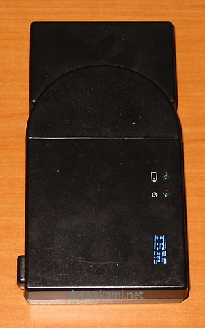
 This is a picture of the External Battery Charger (FRU 11J9003) with the adapter for the 600-series battery (FRU 02K6501). This top view shows the two LEDs and the DC power jack on the bottom left.
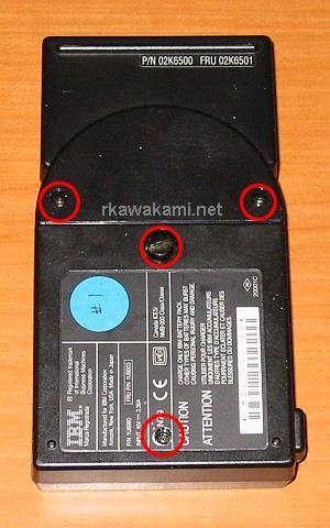 A bottom view shows that there are four screws. Only two of them actually keep the charger together. The two small screws at the top of the picture are on the battery adapter and don't need to be removed. The large thumbscrew, along with the one hidden underneath the label is what holds the charger's shell in place.
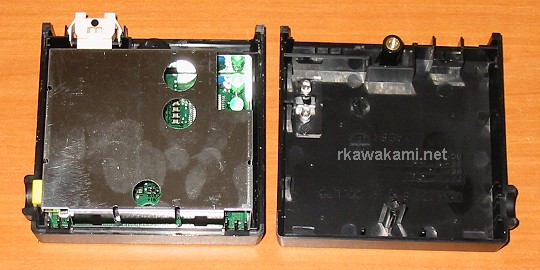 The adapter has a connector which plugs into the charger (seen at the top left of this picture). Separating the charger's shell reveals a metal shield surrounding the charger's printed circuit board.
 The shield simply lifts off.
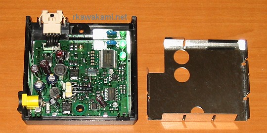
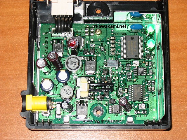 This is a closeup of charger's circuit board. I have not yet tried to identify the main ICs, but it's more sophisticated than what I originally thought was in here.